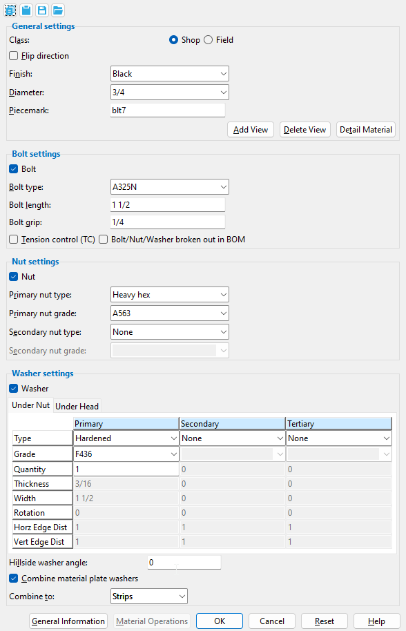
Material Bolt Edit window
- General Overview
- Tips and Tricks
- Related Tools
![]() Copy, Paste, Save, Load buttons:
Copy, Paste, Save, Load buttons:
- The position of these "form" buttons on the window tells you what settings they apply to. Click here for more information.
- You can
 Copy the settings on this window, then
  Paste those settings to a different edit window of the same type.
- You can
 Save the settings on this window to a file stored in a global folder that is used by your current version of SDS2. Give the file a name that will help other users identify its purpose. You can
  Load a saved file to replace the settings on this window (except Piecemark) with the settings that are stored in the file you select.
- When editing multiple windows at the same time, Paste and Load replace mixed entries to a single field with a single entry. Copy and Save ignore fields with mixed entries, treating them as if they have no entry or do not exist.
------ General settings ------
|
' Field ' bolts and ' Shop ' bolts can be displayed in different colors. Setup for this is done on the Member, Material, Bolt and Weld Colors window. |
'
Field ' bolts are sometimes referred to as "site bolts." By definition, they are bolts that are applied in the field, at the construction site. Generally they are shipped loose to fasten together materials that are parts of different members. Field bolts are not drawn on member details -- only the holes they go into are drawn. They do appear in the member bill of material. Field bolts are associated with the first member that is selected in a Model > Bolt > Add operation.
'
Note: Even though changing the bolt " Class " on a system connection does not make the connection graphical , the change is preserved through Process and Create Solids .
Also see: Home > Project Settings > Job > Bolts, Washer, and Holes > Bolt Settings > Default bolt class . Field bolts can optionally be listed in the member bill of material.
Status Display: Bolt status > Field bolt
Report Writer: MemberMaterial.Bolt.IsFieldBolt
Advanced Selection: IsFieldBolt
Parametric module: IsFieldBolt
If this box is checked (
) when you press " OK " to close this window, the bolt you are editing will be flipped so that its head and nut change places. When you open this window again, the box will be not checked.
If the box is not checked (
) when you press " OK " to close this window, the bolt direction will remain as it is shown in your current view.
Note: You can change the bolt direction on a system connection without making the connection graphical . Your change is preserved through Process and Create Solids .
Finish: Black or Zinc/Aluminum ASTM F1136 or Mechanically galvanized or Hot dipped galvanized .
Setup: When a member's "Surface finish" is not galvanized, the " Finish " that is applied to bolts that are generated automatically is ' Black '. When a member's "Surface finish"is galvanized, the " Finish " is the " Bolt finish " (either ' Mechanically galvanized ' or ' Hot dipped galvanized ') that is specified at Home > Project Settings > Fabricator > Detailing > Galvanizing Settings .
Note: You can change the finish on a system connection without making the connection graphical . Your change is preserved through Process and Create Solids .
Status Display: Bolt status > Bolt finish
Report Writer: MemberMaterial.Bolt.FinishDescription
Diameter: The diameter (inches or mm) of the shank of the bolt. When a user Adds a 3D bolt to a hole, the diameter of that bolt is based on the hole " Diameter " and " Type " of the hole that the bolt is inserted into.
| diameter |
|
To make an entry: You can either type in a diameter or select a bolt diameter from the combo box (
). Diameters that are listed come from Home > Project Settings > Job > Bolts, Washers, and Holes > Bolt Settings > the " Available bolt diameters " list.
Warning: Changing a bolt's " Diameter " does not change the hole size for that bolt.
Status Display: Bolt status > Bolt diameter
Report Writer: MemberMaterial.Bolt.Diameter
Advanced Selection: Diameter
Parametric module: Diameter
Piecemark: Blank or any text string (up to 61 characters). This is the submaterial mark of a bolt that was added using Material Add Bolt.
If this field is left ' blank ', then when this material bolt is generated (after you press " OK "), piecemarking looks for material bolts in the current Job that are physically identical to this material bolt and assigns to this material bolts the same mark assigned to those materials. If no matching material bolts are found, piecemarking assigns this material bolt a piecemark using the appropriate piecemark prefix listed in Home > Project Settings > Fabricator > Piecemarking > Member and Material Piecemarking > the " Prefixes " tab.
Any ' text string ' that you enter must be unique. Validation does not let you enter a piecemark that has already been assigned to bolt materials. If you are doing an Add Material , a bolt material piecemark entered here only applies if the bolt material you are adding is unique -- if the bolt material is exactly the same as previously added bolt materials, the new bolt material gets the piecemark of those previously added bolt materials. On the other hand, if you are doing an Edit Material , all bolt materials that are exactly like this material are re-assigned the unique mark you enter when this material is generated (after you press " OK "). The piecemark you enter remains a system piecemark , which means that it may be changed if you later edit a bolt material just like this one and give that bolt material a different piecemark.
Note: A submaterial mark is not yet assigned when this window opens for a material bolt add operation. A piecemark will probably have been assigled if you open this window using Edit Material or Review 2D Items . For the current quantity of materials assigned this piecemark, see the " Current quantity " listed on this material's General Information window.
Advanced Selection: MinorMark
Parametric module: MinorMark
Report Writer: MemberMaterial.Material.MinorMark
Special Buttons for Detailing this Material
(these do not appear for Add operations)

This button opens a window with a list of preset views . Each preset view that you select on this list is drawn on the submaterial detail when you Detail Submaterial . This button opens a list of views you can delete. If the material has only one view, you get a warning instead of a list of views since you cannot delete the current view. This button does a Detail Submaterial on this material. Newly added views are drawn on the detail. Deleted views are not drawn.
------ Bolt settings ------
|
|
If this box is checked (
If the box is not checked (
Tip: Use Add Bolt Point to Point and check " Nut " and " Washer " -- but not " Bolt " -- to add a nut and washer to a threaded round bar.
Report Writer: MemberMaterial.Bolt.HasBolt
Bolt type: A325N or A325SC or A325S , etc. This is the bolt type of the bolt whose settings are defined on this window.
Setup: This list box (
Also see: The default " Bolt type " is the " Preferred bolt type " set on the Edit Hole window for the hole group to which this bolt was added.
Status Display: Bolt status > Bolt type and Bolt status > Bolt material
Report Writer: MemberMaterial.Bolt.BoltTypeDescription
Advanced Selection: BoltType or BoltTypeDescription
Parametric module: BoltType or BoltTypeDescription
Bolt length: The distance (in the primary dimension " Units " or other units ) from the inside of the bolt head to the end of the bolt shank. The bolt' s head thickness is not included in the calculation of bolt length because head thickness may vary among bolt manufacturers.
| length |
|
Defaults: The length that is automatically entered here is calculated based on the thickness of the materials into which the bolt is inserted, the number and thickness of washers, the thickness of the nut, and the amount of bolt stick-thru.
Validation: Metric bolts are manufactured in increments of 5 mm. Imperial bolts are manufactured in increments of 1/4 inch for lengths up to 5 inches, and in increments of 1/2 inch thereafter. If the box is checked (in setup) for " All imperial bolt lengths in 1/2 inch increments ," any entry that you make here which is not an increment of 1/2 inch will be increased to the nearest 1/2 inch when you Tab out of this field and the " Bolt grip " field.
Status Display: Bolt status > Bolt length
Report Writer: MemberMaterial.Bolt.Length
Advanced Selection: Length
Parametric module: Length
Bolt grip: The distance (in the primary dimension " Units " or other units ) between the inside of the bolt head and inside of the nut. If there are washers on the bolt, the bolt grip is measured from the inside of the washers.
|
g = grip |
Note: The grip that is automatically entered here is calculated by adding together the thicknesses of the materials into which the bolt is inserted. If you change the " Bolt grip ," the " Bolt length " may be adjusted to satisfy the " Minimum stick-through " and " Maximum stick-through " settings in Bolt Settings . Field clearance gaps that are less than or equal to 3/32 inch are ignored when calculating the bolt grip.
Status Display: Bolt status > Bolt grip
Report Writer: MemberMaterial.Bolt.Grip
Advanced Selection: Grip
Parametric module: Grip
|
|
||||
| Only TC field bolts are displayed with the splined end. TC shop bolt ends look the same as non-TC bolts. | |||||
If this box is checked (
If the box is not checked (
Note: Even though changing to and from TC bolts on a system connection does not make the connection graphical , your change is preserved through Process and Create Solids .
Status Display: Bolt status > Tension control
Report Writer: MemberMaterial.Bolt.IsTensionControl
Advanced Selection: IsTensionControl
Parametric module: IsTensionControl
Bolt/Nut/Washer broken out in BOM: ![]() or
or ![]() . This applies when you Detail Members . This option is disabled ( grayed out ) when " Tension control (TC) " is enabled (
. This applies when you Detail Members . This option is disabled ( grayed out ) when " Tension control (TC) " is enabled ( ![]() ).
).
|
||||||
| These examples are taken from a member's bill of material. To open a particular member's bill of material ( bill editor ), start up the Drawing Editer > open the desired member detail > choose Objects > Bill of Material > Edit Bill . |
If this box is checked (
If the box is not checked (
Defaults: For shop bolts, the choice made here sets the default for " Bolt/Nut/Washer broken out in BOM " on the Bolt Edit window in the Drawing Editor . The default choice made here (for both shop and field bolts) comes from Home > Project Settings > Fabricator > Detailing > Bolt Detailing Settings > " Bolt/Nut/Washer broken out in BOM ."
Tip for editing: Set " View By " in the Model Tree to ' Member PIecemark ' and find the member in the Model Tree whose BOM bolt callout method you want to change. The shop bolts and field bolts associated with a member are enumerated in the Model Tree .
Note: Even though changing whether or not the bolt, nuts, and washers are "broken out" on a system connection does not make the connection graphical , your change is preserved through Process and Create Solids .
------ Nut settings ------
 |
 |
If this box is checked (
If the box is not checked (
Tip: Use Add Bolt Point to Point and check " Nut " and " Washer " -- but not " Bolt " -- to add a nut and washer to a threaded round bar.
Report Writer: MemberMaterial.Bolt.HasNut
Primary nut type: None or Heavy hex or Heavy square or Jam . The primary nut is the nut that is closest to the material that is being fastened. A primary heavy hex nut is assumed to be attached to a bolt and, therefore, its existence is not automatically called out in the member bill of material or on the detail.
|
|
|
' None ' generates the bolt without a nut.
' Heavy square ' generates a square-shaped nut.
' Heavy hex ' generates a hexagon-shaped nut.
' Jam ' generates a jam nut.
Status Display: Bolt status > Primary nut type
Report Writer: MemberMaterial.Nut.PrimaryNutTypeDescription
Primary nut grade: Any grade entered to the " Nuts " tab at Home > Project Settings > Job > Nut and Washer Schedule for the selected type (' Heavy square ' or ' Heavy hex ' or ' Jam ') can be selected on the list box ( ![]() ) for this field.
) for this field.
Setup: The default grade that is applied to a particular " Bolt type " is the " Nut Grade " that is selected at Home > Project Settings > Job > Bolts, Washers, and Holes > Bolt Specifications . All bolts defined on the Bolt Specifications use a single heavy hex nut (the primary nut).
Status Display: Bolt status > Primary nut grade
Secondary nut type: None or Heavy hex or Heavy square or Jam . The secondary nut is the nut that is closest to the end of the bolt. SDS2 does not design secondary nuts by default. This option is provided so that you can add them yourself. Secondary nuts are called out in the " Remarks " column in the bill of material and may optionally be called out on the member detail.
|
|
|
' None ' prevents a secondary nut from being generated.
' Heavy square ' generates a hexagon-shaped secondary nut. The nut is called out as a "HHNT" on the detail and in the bill of material.
' Heavy hex ' generates a square-shaped secondary nut. The nut is called out as a "HSNT" on the detail and in the bill of material.
' Jam ' generates a secondary jam nut. The nut is called out as a "JMNT" on the detail and in the bill of material.
Status Display: Bolt status > Secondary nut type
Setup: List washers & secondary nut with shop bolts on details ( Bolt Detailing/Fabricaton Options )
Setup: List washers & secondary nut with field bolts on details ( Bolt Detailing/Fabricaton Options )
Report Writer: MemberMaterial.Nut.SecondaryNutTypeDescription
Secondary nut grade: Any grade entered to the " Nuts " tab at Home > Project Settings > Job > Bolts, Washers, and Holes > Nut and Washer Schedule for the selected type (' Heavy square ' or ' Heavy hex ' or ' Jam ') can be selected on the list box ![]() )
)
Status Display: Bolt status > Secondary nut grade
------ Washer settings ------
|
|
If this box is checked (
" Type ." If the box is not checked (
Tip: Use Add Bolt Point to Point and check " Nut " and " Washer " -- but not " Bolt " -- to add a nut and washer to a threaded round bar.
Report Writer: MemberMaterial.HasWasher
| || Under Nut || Under Head || |
| || Primary || Secondary || Tertiary || |
|
| The "primary" position is closest to the steel being fastened. The "secondary" position is the next closest. The "tertiary" washer is closest to the end of the bolt (its nut or head). |
Type: None (no washer in that position) or Hardened or Square plate or Round plate or Bevel or Flat or Hillside or Direct tension indicator or Heavy plate or Double thick hardened or Material Plate . The thicknesses of these washers are set in Washer Settings . For other bolts, the washers that are used are specified in Washer Settings , with the exception that additional washers may be added if the box is checked for " Add washers to prevent shank-out when needed ."
| Type | shape | BOM | setup thickness | related settings |
| hardened |
|
HD | " Hardened washers " | |
| square
plate |
|
PL | " Plate washers " |
" Thickness " " Width "
" Rotation " |
| round
plate |
|
RPL | " Plate washers " | " Thickness " " Width " |
| bevel |
|
BVL | " Bevel washers " | " Rotation " |
| flat |
|
FL | " Flat washers " | |
| hillside |
|
HLS | - | used for rod bracing |
| direct tension indicator |
|
DTI | " Direct tension indicator " | |
| heavy
plate |
|
HVPL | " Heavy plate washers " |
" Thickness " " Width "
" Rotation " |
| double thick hardened |
|
DTHD |
" Double thickness
hardened " |
see introductory comments |
| material plate |
|
(see note) | " Material plate washers " |
" Horz Edge Dist "
" Vert Edge Dist " |
Note: Material plate washers aren't listed in the " Remarks " column of the BOM. They are listed as submaterials.
Status Display: Bolt status > Primary washer under nut and Secondary washer under nut and Tertiary washer under nut
Report Writer: MemberMaterial.Bolt.PrimaryHeadWasher.TypeDescription
Report Writer: MemberMaterial.Bolt.SecondaryHeadWasher.TypeDescription
Report Writer: MemberMaterial.Bolt.TertiaryHeadWasher.TypeDescriptionReport Writer: MemberMaterial.Nut.PrimaryNutWasher.TypeDescription
Report Writer: MemberMaterial.Nut.SecondaryNutWasher.TypeDescription
Report Writer: MemberMaterial.Nut.TertiaryNutWasher.TypeDescription
Grade: Any grade that has been entered to the " Washers " tab at Home > Project Settings > Job > Bolts, Washers, and Holes > Nut and Washer Schedule for the selected type (' Hardened ' or ' Bevel ' or ' Load ' or etc.) can be selected on the list box ![]() )
)
Setup for system connection bolts: The type of washer that is applied to a " Bolt type " is set at Home > Project Settings > Job > Bolts, Washers, and Holes > Washer Settings . The default grade that is applied to a washer of a particular type is the first grade for a washer of that type that is listed in the " Washers " tab at Home > Project Settings > Job > Bolts, Washers, and Holes > Nut and Washer Schedule .
Quantity: The number of washers that are in this position.
Note: You can change the quantity of washers on a system connection without making the connection graphical. Your change is preserved through Process and Create Solids .
Report Writer: MemberMaterial.Bolt.PrimaryHeadWasher.Quantity
Report Writer: MemberMaterial.Bolt.SecondaryHeadWasher.Quantity
Report Writer: MemberMaterial.Bolt.TertiaryHeadWasher.QuantityReport Writer: MemberMaterial.Nut.PrimaryNutWasher.Quantity
Report Writer: MemberMaterial.Nut.SecondaryNutWasher.Quantity
Report Writer: MemberMaterial.Nut.TertiaryNutWasher.Quantity
Thickness: The thickness (in the primary dimension " Units " or other units ) of the square plate or round plate washer or heavy plate or double thick hardened washer.
t = thickness

Note: You can change the washer thickness on a system connection without making the connection graphical . Your change is preserved through Process and Create Solids .
Report Writer: MemberMaterial.Bolt.PrimaryHeadWasher.Thickness
Report Writer: MemberMaterial.Bolt.SecondaryHeadWasher.Thickness
Report Writer: MemberMaterial.Bolt.TertiaryHeadWasher.ThicknessReport Writer: MemberMaterial.Nut.PrimaryNutWasher.Thickness
Report Writer: MemberMaterial.Nut.SecondaryNutWasher.Thickness
Report Writer: MemberMaterial.Nut.TertiaryNutWasher.Thickness
Width: The length or width of a square washer, or the diameter of a round plate washer. Your entry is interpreted as being in the primary dimensioning " Units ."
w = width
Note: You can change the washer width on a system connection without making the connection graphical . Your change is preserved through Process and Create Solids .
Report Writer: MemberMaterial.Bolt.PrimaryHeadWasher.Width
Report Writer: MemberMaterial.Bolt.SecondaryHeadWasher.Width
Report Writer: MemberMaterial.Bolt.TertiaryHeadWasher.WidthReport Writer: MemberMaterial.Nut.PrimaryNutWasher.Width
Report Writer: MemberMaterial.Nut.SecondaryNutWasher.Width
Report Writer: MemberMaterial.Nut.TertiaryNutWasher.Width
Rotation: A positive or negative (-) number of degrees (from 999999 to - 99999 ). A rotation can be applied when ' Square plate ' or ' Bevel ' or ' Hillside ' or ' Heavy plate ' is the selected " Type " of washer.
0 degrees
 |
10 degrees
 |
25 degrees
 |
45 degrees
 |
' 0 ' degrees makes the edges of the washer parallel with the edges of your computer screen (assuming that the head of the bolt is shown flat on your computer screen).
A positive number rotates the washer counterclockwise when you are looking at the head of the bolt. Point 1 is the head end of the bolt grip in an Add Bolt Point to Point operation.
A negative number rotates the washer clockwise when you are looking at the head of the bolt.
Report Writer: MemberMaterial.Bolt.PrimaryHeadWasher.Rotation
Report Writer: MemberMaterial.Bolt.SecondaryHeadWasher.Rotation
Report Writer: MemberMaterial.Bolt.TertiaryHeadWasher.RotationReport Writer: MemberMaterial.Nut.PrimaryNutWasher.Rotation
Report Writer: MemberMaterial.Nut.SecondaryNutWasher.Rotation
Report Writer: MemberMaterial.Nut.TertiaryNutWasher.Rotation
Horizontal Edge Distance: The horizontal distance (in the primary dimension " Units " or other units ) from the nearest vertical edge of the material plate washer to the center of the hole.This applies when ' Material plate ' is the selected " Type " of washer.
|
HED = horizontal edge distance |
Vertical Edge Distance: The vertical distance (in the primary dimension " Units " or other units ) from the nearest horizontal edge of the material plate to the center of the hole. This applies when ' Material plate ' is the selected " Type " of washer.
|
VED = vertical edge distance |
Hillside washer angle: positive or negative number of degrees (from 999999 to -99999 ). This angle can be applied when ' Hillside ' is the selected " Type " of washer.
|
|
|


Report Writer: MemberMaterial.Bolt.HillsideWasherAngle
Combine material plate washers: ![]() or
or ![]() . This choice can be applied when ' Material Plate ' is the selected " Type " of washer.
. This choice can be applied when ' Material Plate ' is the selected " Type " of washer.
|
When material plate washers are not combined, each bolt gets a separate washer. |
If this box is checked (
If the box is not checked (
Also see: " Combine material plate washers " on the Material Plate Washer window.
Combine to: Single Plate or Strips . This choice can be applied when ' Material Plate ' is the selected " Type " of washer and when " Combine material plate washers " is checked ( ![]() ).
).
|
|

Single Plate : Plate washers are combined into a single plate.
Strips : Plate washers are combined to a strip per column of bolts.
Also see: " Combine to " on the Material Plate Washer window.
" General Information " applies to material bolts only.
The " Properties " button at the bottom of the General Information window lets you Edit Properties for a material bolt.
"Material Operations" opens the Material Operations window.
Tip: You can use the Material Operations window to delete or edit a stored material operation.
Note: Not all material operations are stored in the Material Operations window. Material Fit Exact, Material Fit Cope, Material Fit Notch, and Cut Layout are the only material operations that are stored here.
"OK" (or the Enter key) closes this window and applies the settings on it to the material(s).
Defaults: Even if you did not make any changes on this window, pressing " OK " causes many of the " General settings " on this window to be applied as the defaults for the next material of the same type that is added in your current session of Modeling .
If you opened this window to edit a single material ( single-edit ), the Change All Options & Warning List opens after you press the " OK " button. You can use that window to cancel your changes or, if other materials with the same submaterial piecemark exist, apply your changes to those other materials. Also, if a Cut On Plane or related cutting/bending/fit operation (that does not get stored in the Material Operations window) was previously done on this material, you are given the option to undo that operation.
If you opened this window to edit multiple materials ( multi-edit ), the Change All Options & Warning Listdoes not open after you press the " OK " button. Also, if a Cut On Plane or related cutting/bending/fit operation (that does not get stored in the Material Operations window) was previously done on this material, you are not given the option to undo that operation.
"Cancel" (or the Esc key or the ![]() button) closes this window without saving any changes.
button) closes this window without saving any changes.
Possibilities: If you are adding a new material, " Cancel " brings you back to the work point location step ( step 2 ) in the add operation. For an edit material operation, " Cancel " ends the operation.
Tip: When you open this window to review information only -- and you do not want to set the defaults for the next-added rectangular plate -- the best way to close this window is to press " Cancel. "
"Reset" undoes all changes made to this window since you first opened it. The window remains open.
Note: The settings shown on this window when it first opens for the adding of a material are the settings of the last-added or last-edited material of the same type (unless you exit Modeling in the meantime).
-
This window is read-only if any material bolt you are editing is part of a member that has its " Model complete " date set and ' Restrictive ' is selected.
- Bolts can be added as material bolts as well as bolts.
- Bolt Settings ( Home > Project Settings > Job )
- Bolt Specifications ( Home > Project Settings > Job )
- Material bolts (adding a bolt as a material)
- Bolt Edit (editing a bolt)
- Nut and Washer Schedule ( Home > Project Settings > Job )
- Washer Settings ( Home > Project Settings > Job )

